Technology
The history of GPR dates back to the beginning of the last century. GPR’s predecessor, the telemobiloscope, was patented by Christian Hülsmeyer in 1904 and was the first device capable of detecting distant objects using radio waves. The first written evidence of the use of GPR dates back to 1929, when it was used to estimate the thickness of glacial ice in Austria. The study of ice, both in the mountains and in the polar regions, continued until the 1970s, and at that time GPR was a quasi-geophone that gradually evolved into the modern GPR used in coal and salt mines and on the Apollo 17 mission to the Moon. The first documented successful use of GPR in archaeology – treasure hunting – dates back to 1978. In particular, Victorio Peak in New Mexico was explored to identify caves, tunnels and other cavities beneath the mountain that would match the legend of hunter Milton Noss and his possible treasure trove. The explosion of interest in GPR around the world began in the nineties and continues today. Today, GPR is considered to be the geophysical method with the widest range of applications.
Today, GPR is also widely recognized as an effective and reliable technology for underground utility surveys, and an increasing number of countries have included GPR in their underground infrastructure survey regulations. GPR can provide a very true picture of the area to be surveyed, as it provides thousands of times more measurement points than an electromagnetic tracer. In addition, GPR is less sensitive to external noise and can detect underground utility networks even in areas where they are close together.
GPR is also able to detect all kinds of objects that are different from the environment around it, as well as different layers of soil. More specifically, GPR measures the speed of radio waves, which varies from material to material, and can therefore distinguish between different objects and layers.
The main components of a GPR are the control unit, the antenna and the battery.
The control unit generates and controls pulses of electromagnetic waves. The control device usually also has a built-in computer that receives the reflected pulses, stores them and performs the primary processing. Most control devices also have a display that allows the user to set the GPR settings and monitor the survey data in real time.
The GPR transmitter antenna sends electromagnetic pulses to the ground. This energy penetrates deeper into the ground, but some of this energy is reflected back from objects other than the ground. The reflected energy is captured by the receiver’s antenna and measured for its intensity and the time it took to pass through the ground.
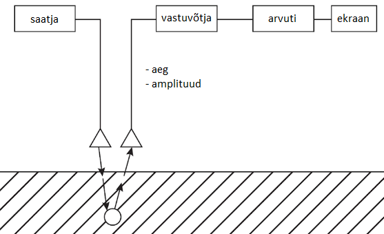
Figure: How the GPR works
To obtain information about objects at different depths, GPR collects several hundred readings of electromagnetic reflections at a single point in a sequence. Depending on the oscilloscope technology used in the GPR, each reading is obtained either by sending out a new pulse (Equivalent-Time Sampling) or by collecting all the readings in a single pulse (Real-Time Sampling). This technology determines the maximum speed of movement of the GPR during data collection.
A set of scans, or A-scan, is compiled from all the samples collected from a single point.
The A-scan can be used to determine the parameters of the reflected wave at that particular location (x, y). This provides important information when comparing the parameters of adjacent measurement points. It can also be used to see the strength and polarity of the amplitude at all heights (z). Depending on the task of the survey, A-scans are collected and generated from these samples, usually every 1 to 5 cm. All GPRs have the possibility to configure whether pulses are sent to the ground automatically at a fixed distance or time, or manually.
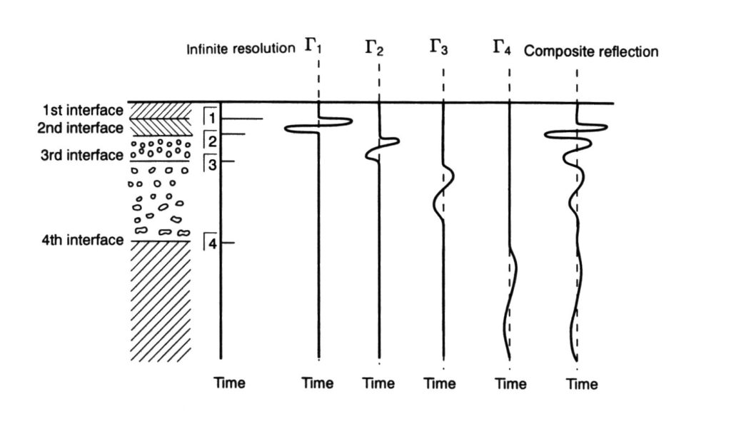
Figure A: A-scanning (D. J. Daniels, 2004)
Moving the GPR along the ground and juxtaposing the A-scans to each other produces a matrix of electric fields, called the B-scan. The B-scan can be used to accurately detect and position targets. This is the main method for accurately locating the position (x, y, z) of underground communications. Depending on the orientation of the linear target (pipe, cable, etc.) with respect to the scan line, the B-scan will show the target as a hyperbola, a partial hyperbola, or a distinct line.
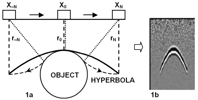
Figure B: B-scanning (Ristic, 2009)
By juxtaposing all the collected B-scans, a 3D matrix or C-scan is formed.
C-scanning allows you to make cuts in the study area both horizontally (time slice) and vertically in the longitudinal and transverse directions. This provides a complete picture of the target location. Different transects from the same area are generally used to determine the exact location of the target.
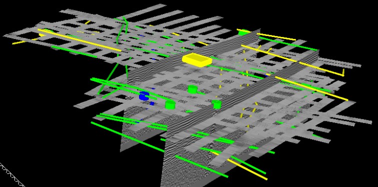
Figure: C-scanning 3D view
As GPR is a geophysical device, its performance is directly influenced by the properties of the soil:
- magnetic susceptibility,
- electrical conductivity,
- dielectric permeability.
Magnetic susceptibility influences the ability of electromagnetic waves to propagate, but as it is low in our natural soil, it generally does not affect the performance of GPR.
The conductivity of the surface has a direct impact on the propagation of electromagnetic waves and thus on the operation of GPR, as it causes energy loss. Due to the electrical conductivity of the soil, the energy emitted by the GPR is scattered in different directions and there is not enough left to penetrate deeper into the soil. As a result, the GPR does not “see” deep enough. For example, saline water has very good conductivity and consequently GPR cannot collect data where seawater has penetrated the ground. Similarly, GPR cannot ‘see through’ dense metal mesh or metal plates.
The dielectric permeability of a surface is a property of the soil on which the GPR relies heavily.
This affects the speed at which electromagnetic waves pass through the surface, by internal resistance and reflection. The dielectric permittivity is an indication of how fast an electromagnetic wave can travel through a given surface.
Different materials have a different dielectric constant, and so electromagnetic waves can propagate through them at different speeds:
|
Material |
dielectric value |
wave speed max (m/ns) |
wave speed min (m/ns) |
|
air |
1 |
0,30 |
0,30 |
|
ice |
4 |
0,15 |
0,15 |
|
dry sand |
4 to 6 |
0,15 |
0,12 |
|
mug |
4 to 7 |
0,15 |
0,11 |
|
granite |
5 to 7 |
0,13 |
0,11 |
|
asphalt |
4 to 8 |
0,15 |
0,11 |
|
clay sand |
7 to 10 |
0,11 |
0,95 |
|
on concrete |
7 to 10 |
0,11 |
0,95 |
|
gravel road |
8 to 14 |
0,11 |
0,80 |
|
möll |
16 to 30 |
0,08 |
0,06 |
|
clay |
25 to 40 |
0,06 |
0,05 |
|
peat |
40 |
0,05 |
0,05 |
|
water |
81 |
0,03 |
0,03 |
Table: Dielectric constant and electromagnetic wave velocity of materials
The GPR measures the time it takes for a pulse to travel from the transmitter’s antenna to the target, and from there to be reflected back to the receiver’s antenna.
Knowing the dielectric permeability of the soil and the time it took for the pulse to reach the target and back, the distance (depth) of the target from the GPR can be calculated.
For example, GPR can map the location and depth of an underground utility network, but it cannot identify exactly which network it is. Depending on the type of GPR, the software and the skill of the interpreter, it may be possible to distinguish between cables and pipes, and between metallic and non-metallic infrastructure, but it is not possible to tell, for example, whether it is a low-voltage, low-voltage or medium-voltage cable. It is also not possible to identify the size and diameter of underground utility networks with sufficient accuracy using GPR.
GPR needs direct contact with the ground to better detect underground objects. For this reason, it is not recommended to use the GPR on ground with thick snow or high grass cover. The GPR is most effective on dry and sandy soils and less effective on wet and clayey soils. GPR can also ‘see through’ concrete well. However, if the metal mesh in the concrete is denser than the wavelength of the GPR, the GPR will not “see through” it.
GPR’s ability to detect objects depends on the frequency of the antenna used.
In general, GPRs used for detecting and mapping underground utility networks have wavelengths between 100 MHz and 1000 MHz, and GPRs for concrete surveys between 1GHz and 3GHz. Lower frequency antennas with frequencies between 40Mhz and 100MHz are also used in geology.
Lower frequencies are able to penetrate deeper. For example, GPR with a 100 MHz frequency antenna can see down to 5 meters, while 1000 MHz can see down to less than 1 meter.
As the wavelength is longer at lower frequencies, the resolution is lower and only larger objects can be detected. Thin cables or small diameter tubes cannot be seen with a low frequency antenna. At higher frequencies, the wavelength is shorter and the resolution is better, allowing the detection of smaller objects, thinner cables and pipes.
However, it is generally not possible to detect conventional utility networks at depths of more than three meters using GPR.
In addition to frequency, wavelength and resolution are affected by the dielectric permeability of the surface. The higher the dielectric value of the surface, the shorter the wavelength and the better the resolution.
|
Antenna frequency MHz |
Maximum depth in meters |
|
Air |
Concrete |
Dry soil |
Compacted soil |
Wet soil |
|
|
|
Dielectric value |
1 |
7 |
9 |
14 |
25 |
|
|
|
Wave speed (m/ns) |
0,3 |
0,12 |
0,1 |
0,08 |
0,06 |
|
100 |
5 |
Wave length/ Resolution (m) |
3,00/0,75 |
1,20/0,30 |
1,00/0,25 |
0,80/0,20 |
0,60/0,15 |
|
200 |
4 |
|
1,50/0,38 |
0,60/0,15 |
0,50/0,13 |
0,40/0,10 |
0,30/0,08 |
|
400 |
3 |
|
0,75/0,19 |
0,30/0,08 |
0,25/0,06 |
0,20/0,05 |
0,15/0,04 |
|
1000 |
1 |
|
0,30/0,08 |
0,12/0,03 |
0,10/0,03 |
0,08/0,02 |
0,06/0,02 |
|
1500 |
0,5 |
|
0,20/0,05 |
0,08/0,02 |
0,07/0,02 |
0,05/0,01 |
0,04/0,01 |
Table: Wavelength and resolution
The GPR is able to pinpoint the exact location of an object because the reflection can only come to the GPR receiving antenna from the exact target. The accuracy with which an object is actually mapped depends on the accuracy of the positioning device and the skill of the GPR data processor.
For example, GPR can generally determine the depth of an underground utility network to within +/- 10%, depending on how homogeneous the soil is in the survey area and how well the dielectric value of the soil can be determined. It is important to keep in mind that GPR measures depth to target.